|
||||||||||||||||||
Raspberry Pi 1-Wire Temperature Sensor Project
BackgroundThis project was inspired when some pipes froze in the crawlspace over the winter when we were not around. The idea is to pick up some 1-wire temperature sensors and drive them with a raspberry pi (RPi), log the readings, make a webpage tracking them, and maybe trigger an incandescent light in the crawlspace if the moving average of the temperature gets below a threshold to heat it up a little bit, safely.
MaterialsStuff I ended up using:
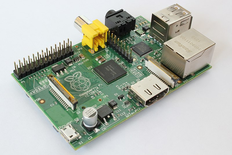
10k Foot ViewA Raspberry Pi is a credit-card sized board that runs Linux and has some useful headers for making stuff. My plan with this project was to use the GPIO headers of the RPi to read the DS18S20s at regular intervals then log the readings into some kind of time series database (after research I used the rrdool and a python interface to it). A cronjob polls the temperature readings every minute. A different cronjob computes a 10-minute moving average and may trigger the incandescent lights. Yet a third cronjob wakes up hourly and drives some graphs on a webpage that are used as a display. Click on most images below for larger views.
Selecting the DS18S20sI did some research on the 1-Wire thermometers and settled on the DS18S20 mainly because of the temperature range and accuracy. They are relatively expensive, unfortunately. The ones I got ran about $4 each(!) (Edit: they can be had much less expensively these days, I saw 10 for $6 on amazon recently). They can be daisy-chained and are meant to be run via twisted pair. Another option is to buy the waterproof 1-wire thermometer (link above) which comes already encased in a waterproof metal casing with a ~3ft black cord running into it. This thing was ~$5 from Amazon when I bought it and it works on the same 1-wire network as the others, no problems. It has three wires: red=power, black=ground, white=data. The datasheet is linked above. Additionally I found a helpful document about how to make the 1-Wire network reliable and this detailed PDF paper about 1-wire protocol and applications.
Setting up the RPi
I'm not going to go into a ton of detail here because you can find all of
this information elsewhere online. The RPi wants to boot from an SD card.
There are several images you can
RPi GPIO -> proto board -> twisted pair bridgeThe RPi has a 26-pin header called GPIO (General Purpose I/O). I read that these pins are basically hooked right to the microprocessor so be really careful about shorting them by accident. It's easy to do when you have dangling wires and might ruin your RPi. An alternative to using the GPIO header is that you can get a little USB bridge dongle that brings your 1-wire network into the USB port on the RPi. I decided to use the GPIO stuff though because I'm brave like that. Here's the GPIO pinout:
I used a 26-pin ribbon cable with a little 26-pin connector crimped onto it to pick up the GPIO header. Attaching the connector was done in my woodworking vice, carefully.
Then I jammed some wires into the other connector end and hooked it all to a
breadboard to see if I could see/read a DS18S20. Everything worked and the
RPi had an entry at
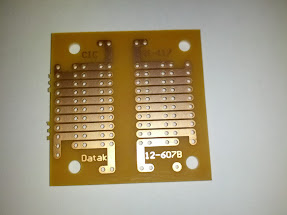
$ cat /sys/bus/w1/devices/10-0008021eb5ed/w1_slave
2a 00 4b 46 ff ff 0d 10 d1 : crc=d1 YES
2a 00 4b 46 ff ff 0d 10 d1 t=20937
The exact format of this data is described in the datasheet linked above. The initial 0x2a and 0x00 are the temperature payload as sign extended two's compliment. Fortunately for you and me, someone already converted it to a temperature in the driver. That's the "t=" business n the second line. Note that there's an implicit decimal point so the above means 20.937°C. Just remember to divide by 1000. It works! Also notice the "crc=d1 YES" bit. If that ends with "NO" then the CRC (cyclical redundancy check, i.e. error-detecting bits) indicate a data error and you should discard the reading and retry. This happens. I had some proto boards lying around here so I soldered some headers that fit the ribbon cable connectors. Neither the proto board nor the header was large enough to pick up all 26 pins from the cable but that's ok because all you needed on the twisted pair network was a power, ground and signal. I originally used power from GPIO pin1 (3v) but later switched to GPIO pin2 (5v) because the document about reliable 1-wire networks recommended 5v and the datasheet for the DS18S20 says it can handle up to 5v. For ground I used GPIO pin9 and for signal I used GPIO pin7 (GPIO 4/GPCLK0).
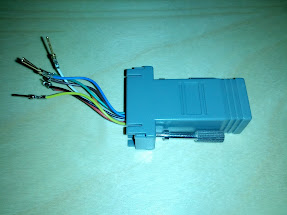
The DS18S20s have a parasitic power mode where you can run them with only two wires: ground and data. The data has a pullup resistor to power and provides enough current to the chip to run it. If you do this you have to ground the unused power pin on the DS18S20. I didn't have a lot of luck with this, though. The DS18S20s would report back bad temperatures way more often when wired this way. That reliable 1-wire network doc also says that for large networks you should use three pins (run power). So I didn't mess with figuring out why parasitic power mode didn't work very much. I took a D-sub to RJ45 adapter and removed the D-sub part so that I just had a eight pins hanging off the back.
Then I cut some cat5e twisted pair cable, crimped an end onto it, plugged it into the D-sub thingy, and used a multimeter to figure out what colors in the twisted pair cable corresponded to what colors on the D-sub thingy. On my setup it looked like this:
You should check your own if you decide to do it this way, though, because I'm sure this is just related to the way I crimp network cables (incidentally, in the same order as the "cat5e twisted pair" colors above). Based on a diagram at hobby boards about 1-wire networks, I decided to use my twisted pair green wire for 5v power, my green/white wire for ground, my blue wire for data and my blue/white wire for ground. I also hooked orange to GPIO1 and brown to GPIO17 with their pairs (orange/white and brown/white) both to ground also. I did this so that I could control far away light switches via a power switch tail or solid state relay later on. Twisting a signal or power wire with ground helps remove interference on the line and will help increase the length of network you can run. I used some hot glue and a zip tie to firmly anchor the D-sub thingy to the proto board and soldered the right pins to the right spots on the board to implement the connections described above. I added a 2k ohm resistor between power and signal and tested it out using a long Ethernet cable with one end cut off and jammed into a breadboard to see if I could still read the thermometer. Here's the final circuit and what it looked like:
As you can see I ended up using a 2k ohm resistor instead of the recommended 4.7k ohm resistor, again on the advice of that reliable 1-wire network doc and some threads I had read online about long distance 1-wire networks. That doc defines "network weight" as the total amount of load (wire, devices) on the network and "network radius" as the distance between the master (RPi) and the most distant slave (DS18S20). I wanted several DS18S20s and had an idea that my network would need at least 20 meters of cable to do what I wanted.
The 1-Wire NetworkMaking the 1-wire network is basically as easy as laying twisted pair cable around wherever you want temperature readings. I chose to use unshielded cat5e twisted pair because I had a roll of it sitting in the closet. First, I took the DS1820s, a short distance of twisted pair cat5e cable, and a RJ45 end and made a little plug-in thermometer. Crimp the end onto the cable then solder the DS1820's three pins to the appropriate color wires on the other side. For me that is DS1820 pin1 (ground) to blue/white, DS1820 pin2 (data) to blue and DS1820 pin3 (power) to green. I used two sizes of heat-shrink tubing to shield the wires from each other and to encase all the wires in a sheath. Be careful when you're doing this not to pre-shrink your heat shrink tubing by getting the soldering iron too close. Also look at your wires carefully; I managed to nick a couple of them when stripping one of the cat5e cables and one of my thermometers would not work until I cut it open and fixed it with some electrical tape...
Once you have your plug in thermometers you can run a normal twisted pair network around the area you want to take temperature readings from. I ordered some twisted pair RJ45 splitters online to facilitate this. I don't know if you can use an old hub if you have one and would love to hear. But definitely do not use a switch because my understanding is that a hub operates on the physical layer whereas a switch is aware of data. Don't worry about the bad reviews people give to RJ45 splitters: as best I can tell they are from dumb people who try to use them to wire up Ethernet instead of using a hub/switch. I terminated my runs with modular surface mount RJ45 jacks that I could plug the little thermometers into.
Software
Once everything was setup the fun part could begin: writing the code. After
some research I found
To setup the rrdtool on the SD card of the RPi you will need to provide the
interval (
% rrdtool create temps.ttd --start 1371018212 --step 60 \
  DS:inside:GAUGE:900:-50:50 \
  DS:outside:GAUGE:900:-50:50 \
  DS:crawlspace:GAUGE:900:-50:50 \
  RRA:AVERAGE:0.5:1:525600 \
  RRA:AVERAGE:0.25:60:87600
This creates three data sources ("inside", "outside" and "crawlspace") that
can store data values between -50 and 50. All are supposed to be provided
once every 60 seconds (--step) and will be considered to be "unknown" if
more than 900 seconds have passed without being set. Values can be stored
anytime after the UNIX timestamp passed to Next, I wrote a simple python utility to poll the temperature of a sensor values and write them into this rrdtool file. Remember to check whether the CRC was valid on your read; if it's not the data is probably corrupt. This happens sometimes:
This thing is called every minute from a cronjob and, as you can see,
puts some data into the
Since
#!/bin/sh

rrdtool graph /home/pi/www/one_day.png \
  --title "Temp (C) at the Cabin, 1d" \
  --start now-1d --end now \
  --width=640 --height=480 \
  --step=60 -v degreesC \
  DEF:temp1=/home/pi/temps.rrd:outside:AVERAGE \
  DEF:temp2=/home/pi/temps.rrd:inside:AVERAGE \
  DEF:temp3=/home/pi/temps.rrd:crawlspace:AVERAGE \
  LINE2:temp1#008000:"outside" \
  LINE2:temp2#800000:"inside" \
  LINE2:temp3#800080:"crawlspace" \
  HRULE:0#0000FF:"freezing"
...
Here's a script that can wake up as a cronjob, compute the 10 minute moving average temperature, and toggle a light switch by setting GPIO pin 17 high or low. That pin goes out over the twisted pair network on the brown wire and can be fed into a power switch tail or a solid state relay to flip a switch. Remember that the GPIO pins are very low current (~18ma) so you can't flip a mechanical relay with one of these directly.
The wifi adapter I linked about from Edimax works with the RPi and doesn't need a powered USB hub. So I used it to avoid running Ethernet down to where I wanted the 1-Wire network to live. Here's another sample of a temperature graph extracted from the RRD (not live). Since I wrote this page originally I've added another temperature sensor to measure how hot the outside hot tub is. I also operate the lights via a wifi "smart" switch in the crawlspace and turn them on if it gets too cold down in the crawlspace in the winter. There are four 75W incandesent bulbs so it helps a bit to warm things up. Send me an email if you're interested in how to set that up and program it.
|
||||||||||||||||||
|
|